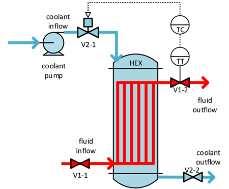
A heat exchanger is a device used to transfer heat between two different mediums. To be exact, in this case, the modelling object is a cross flow heat exchanger that is used for cooling fluid X by using water coolant. The system is shown in Figure 1.


Figure 1. Crossflow heat exchanger used for cooling
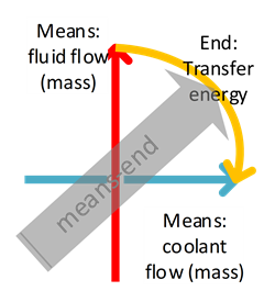
To use an MFM model to represent such a system, one must understand the objective of the system and how the objective is achieved. Through this kind of means-end analysis of the system, different flows can be identified. In this case, the objective is to reduce the fluid temperature by transferring the heat (energy) from the hot fluid to the coolant. This transfer of energy is achieved by transporting both the hot fluid and the coolant through the device of a heat exchanger where the heat transfer happens.


Figure 2. Means-end analysis with the mass and energy flows
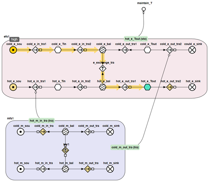
In Figure 3, the MFM model of the heat exchanger is shown. A mass flow structure mfs1 and an energy flow structure efs1 are used. In mfs1, there are two mass flows (hot fluid / red arrow and coolant / blue arrow) provided by the two sources and delivered to the two sinks. The two mass flows are isolated from each other by a barrier function that is provided by the heat exchanger internal tubes.
In the energy flow structure efs1, two energy streams go into the system (one carried by the fluid, and one carried by the coolant), provided by the two source functions in efs1. From the energy perspective, the heat exchanger internal tubes do not serve as a barrier function, but quite the opposite, it allows the energy to pass from the hot fluid to the coolant with a transport function. The energy transfer from the fluid to the coolant is indicated by the yellow arrow in Figure 3.
The two flow structures are connected through mediate relations. The first mediate relation connects mfs1 to the energy flow function cold_e_out_tra2, which means that the outflow of the coolant mediates the energy removal in efs1. In this case, the energy flow function cold_e_out_tra2 is the functional objective. It is realized by the mass flow and with the same coolant inlet temperature. The cooling capacity is related to the coolant flow rate. Similarly, the second mediate relation represents that the fluid flow mediates the delivery of energy from the energy source into the system.


Figure 3. MFM model of the heat exchanger
Causal reasoning
If a high temperature of the hot fluid outlet flow is observed, the information can be interpreted and a proposition asserting that “hot_e_Tout” is “high” shall be made. Then, the causes and effects of this proposition can be generated as dependent propositions based on the model connection. One of the cause propagation path is shown in Figure 4 as an example. This cause path indicates that the high coolant temperature may lead to insufficient cooling of the hot fluid.


Figure 4. Causal reasoning example